Mola Assembly Tips
Expert Guidance for Seamless Building Experiences
Get the most out of your
Mola Structural Kits
Welcome to our Assembly Tips page, where you'll find a comprehensive and ilustrated collection of tips and best practices designed to help you get the most out of your Mola Structural Kits.
Learn how to handle and store components, apply loads in different ways, combine sets for expanded possibilities, and understand the unique magnet behavior that connects the pieces of the system.
Elevate your building experience with detailed instructions and insights, ensuring your Mola performs at its best.
(You can also find some of these instructions in every Mola Structural Kit book/manual)
![]()
Mola products contain small magnets and it's not a toy.
Keep Mola parts away from children, pets and magnetically sensitive items.
Storage Items
Mola Structural Kit Box
Mola Box
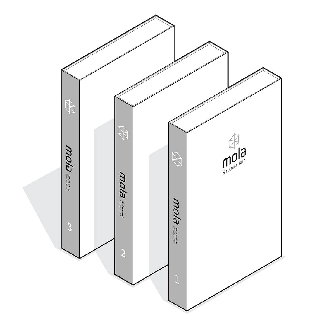
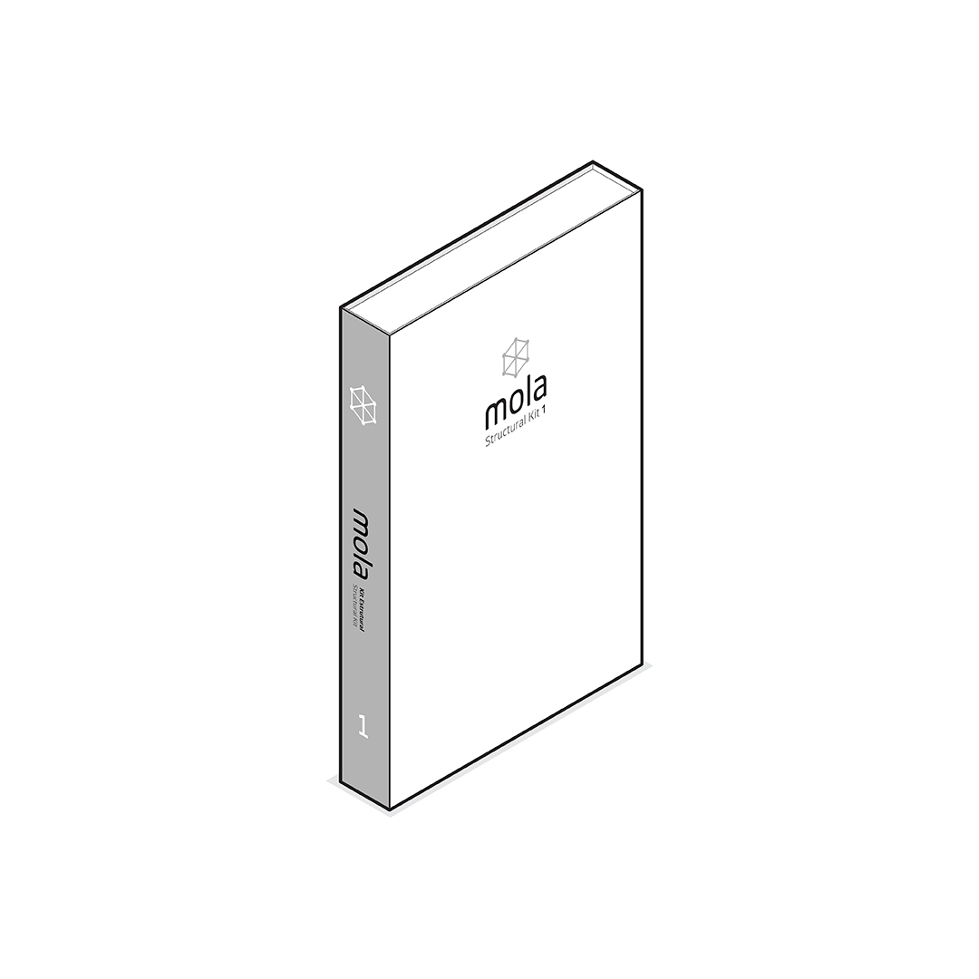
Mola Structural Kits are packed in a rigid and compact box. With a paper and foam construction, resembling the feel and appearance of a book, it surprises with its resistance and durability. This ensures the product stays protected and organized, all in a compact design you can place on your shelf or slip into your backpack to take it anywhere.
Box + Folder
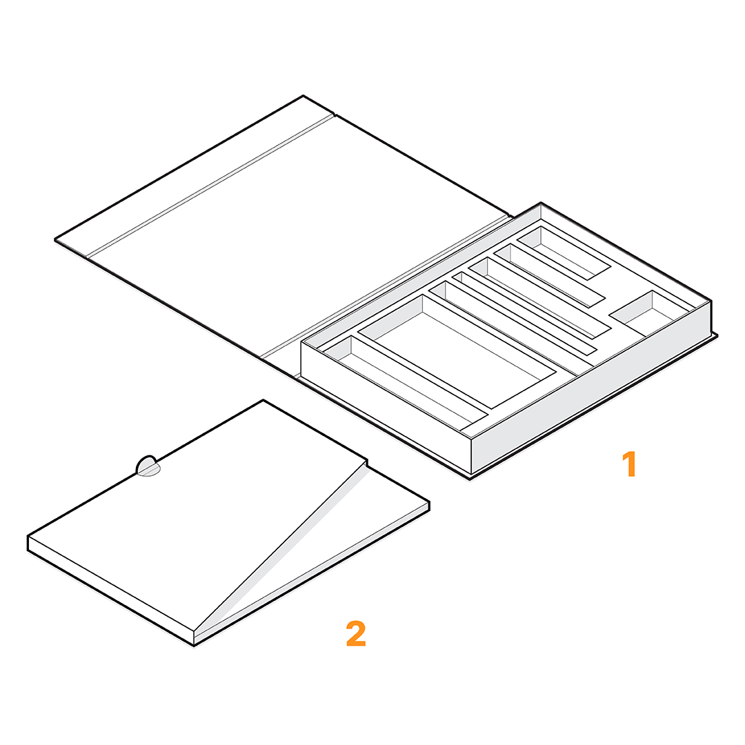
Mola Structural Kits are composed of two storage items: the box and a folder.
- The box has foam custom-made inserts to snugly hold each component of the set in place and protect them during transportation.
- The folder stores the Ground Plate (s) and the book/manual.
Box Closure Instructions
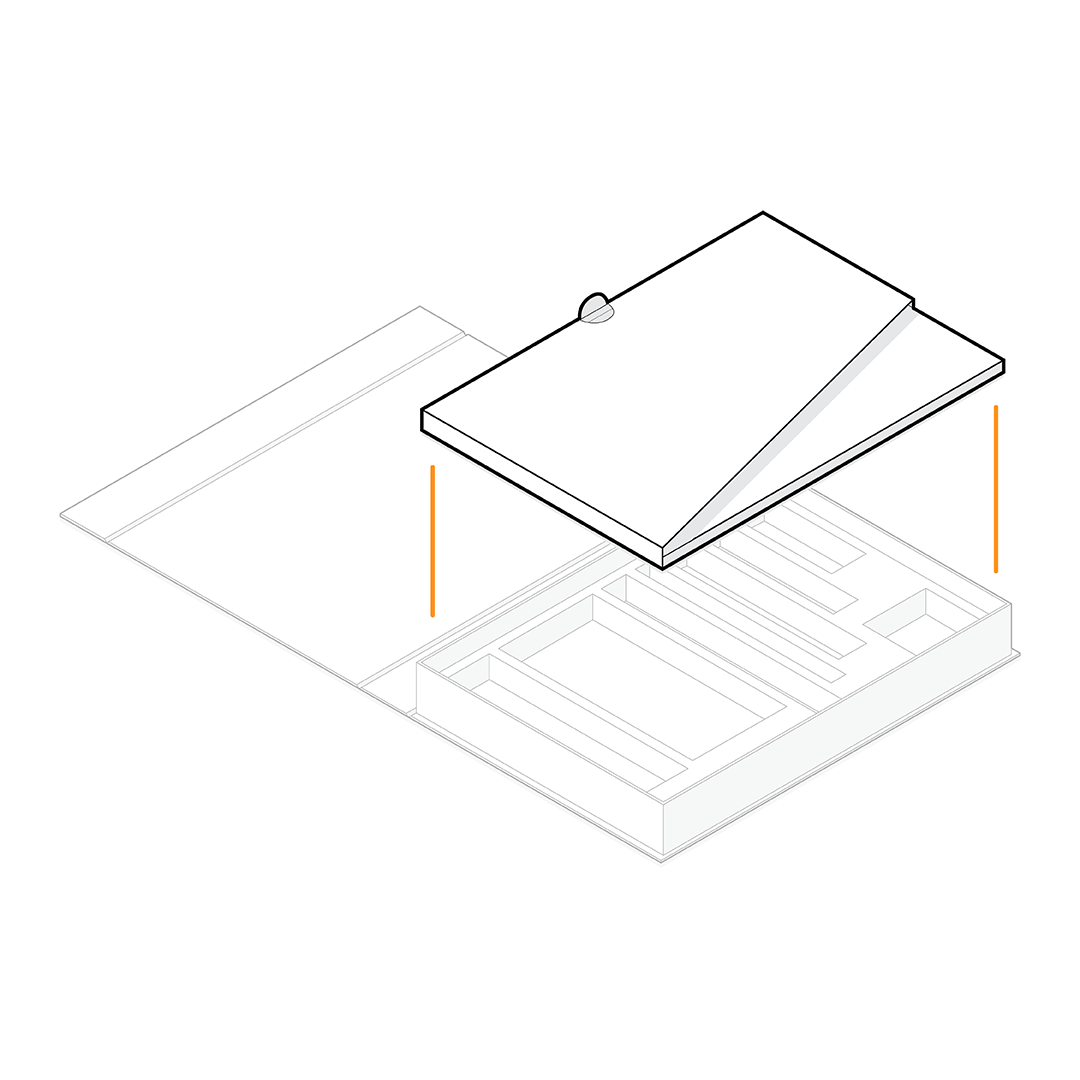
Always place the folder inside the box before closing it! The folder not only holds the Ground Plate and the book/manual but also plays a crucial role in keeping the set components in their specific inserts. If the folder is not placed inside the box, the components may shift or fall out of their designated spaces during transportation and storage.
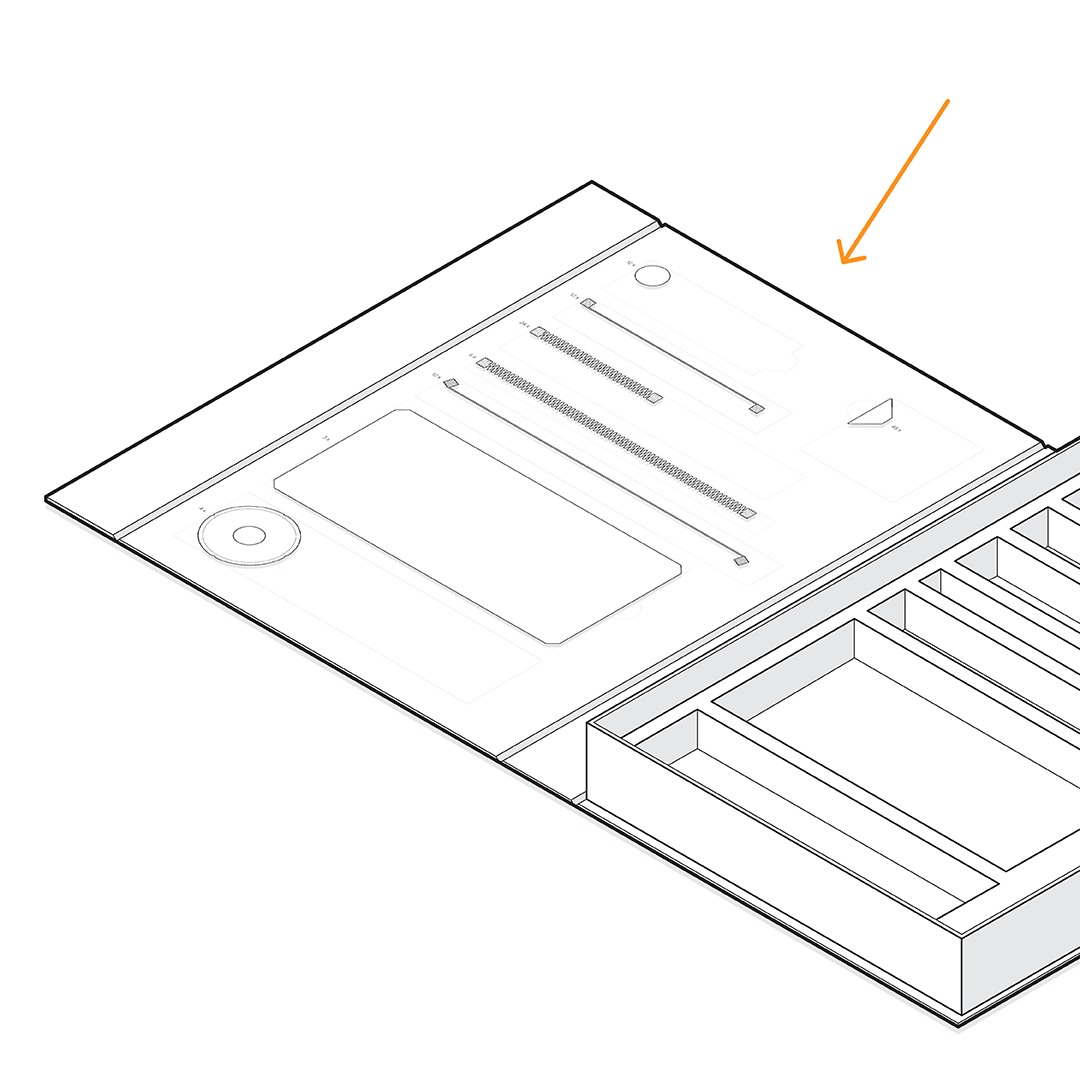
Box Lid
To help you organize and store each component of the set, check the box lid. The lid contains information about the size, quantity and the insert position for each component. This guide ensures that every part is accounted for and properly placed in its designated spot.
Handling Components
Learn about the unique magnet behavior that connects the pieces of the Mola Structural System.
This useful information will help you organize and store the components properly.
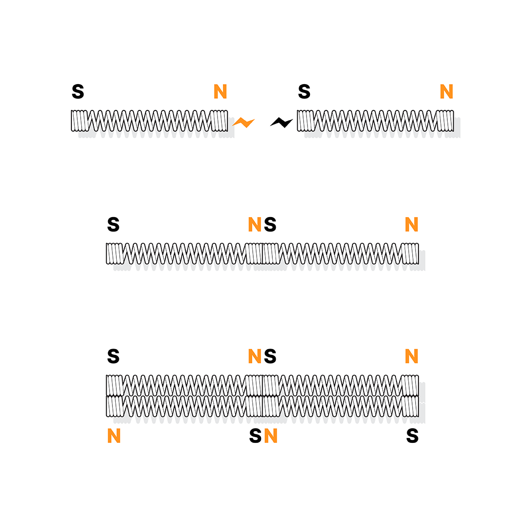
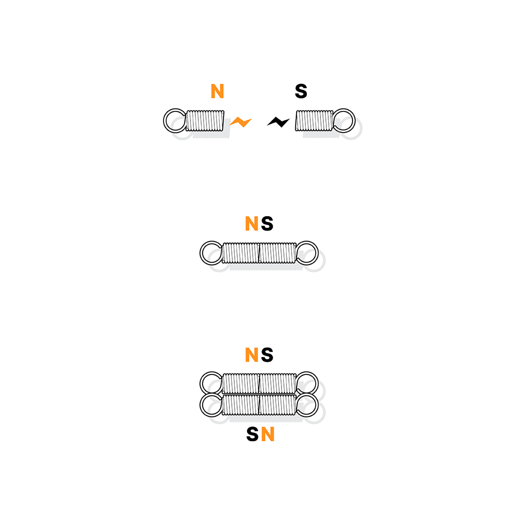
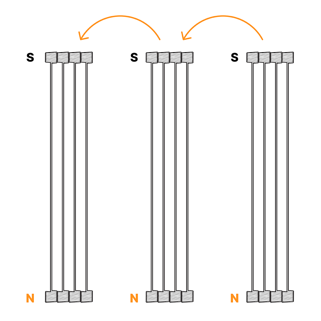
Bars and Diagonals
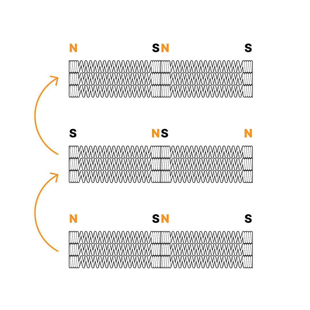
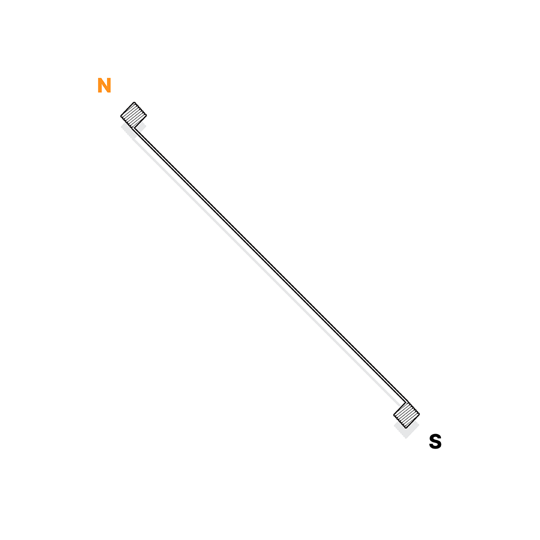
The Bars and Diagonals have magnets at their extremities and these magnets are positioned so that the parts may connect to one another. Thus, each bar or diagonal has ends with opposite magnetic polarity (N, north pole, and S, south pole). Therefore, if there is repulsion between two parts, simply invert one part to perfectly connect them.
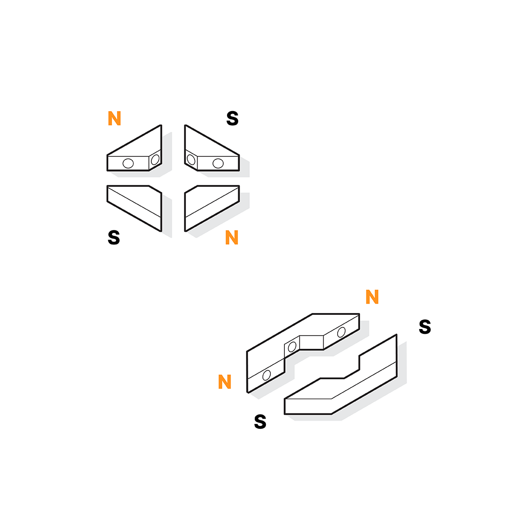
Connections
The Rigid Connections and Continuous Connections feature magnets along their perimeter, positioned to allow the parts to be easily connected. Each part presents a single magnetic polarity in its perimeter and, for their attachment, simply interpolate the parts with opposite polarities.
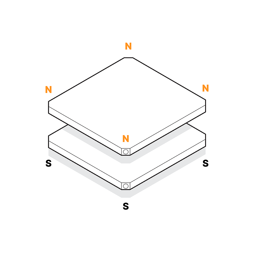
Plates
The Plates also feature magnets along their perimeter, positioned to allow connections. Each plate presents a single magnetic polarity. To stack them up, simply interpolate the parts with opposite polarities.
Cable Connections
The Cable Connections feature a magnet at their extremity, positioned to allow the parts to be easily connected. Each part presents a single magnetic polarity in its extremity and, for their attachment, simply interpolate the parts with opposite polarities.
Handling and Storing Bars and Diagonals
A step-by-step guide to master the organization and storage of bars and diagonals in the box.
This procedure will work for all bar and diagonal elements, regardless of their length.
By following these steps, you can ensure all components will be neatly stored and ready for use.
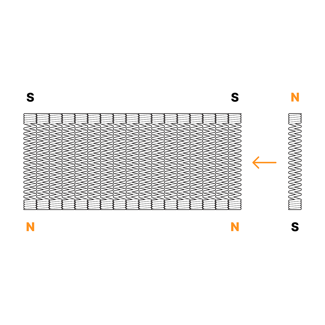
Step 1
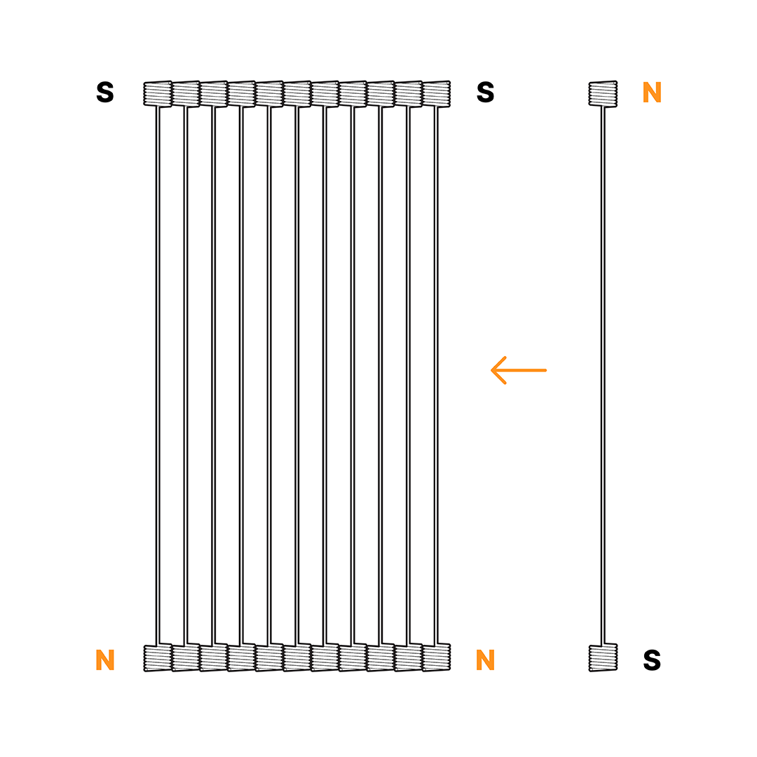
Start by aligning all bars side by side. If there is magnet repulsion between two bars, simply flip one bar to ensure they connect perfectly.
Step 2
Divide the block of aligned bars in half and rotate them until the bars from both sides connect at their extremities.
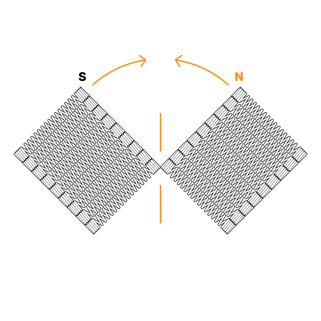
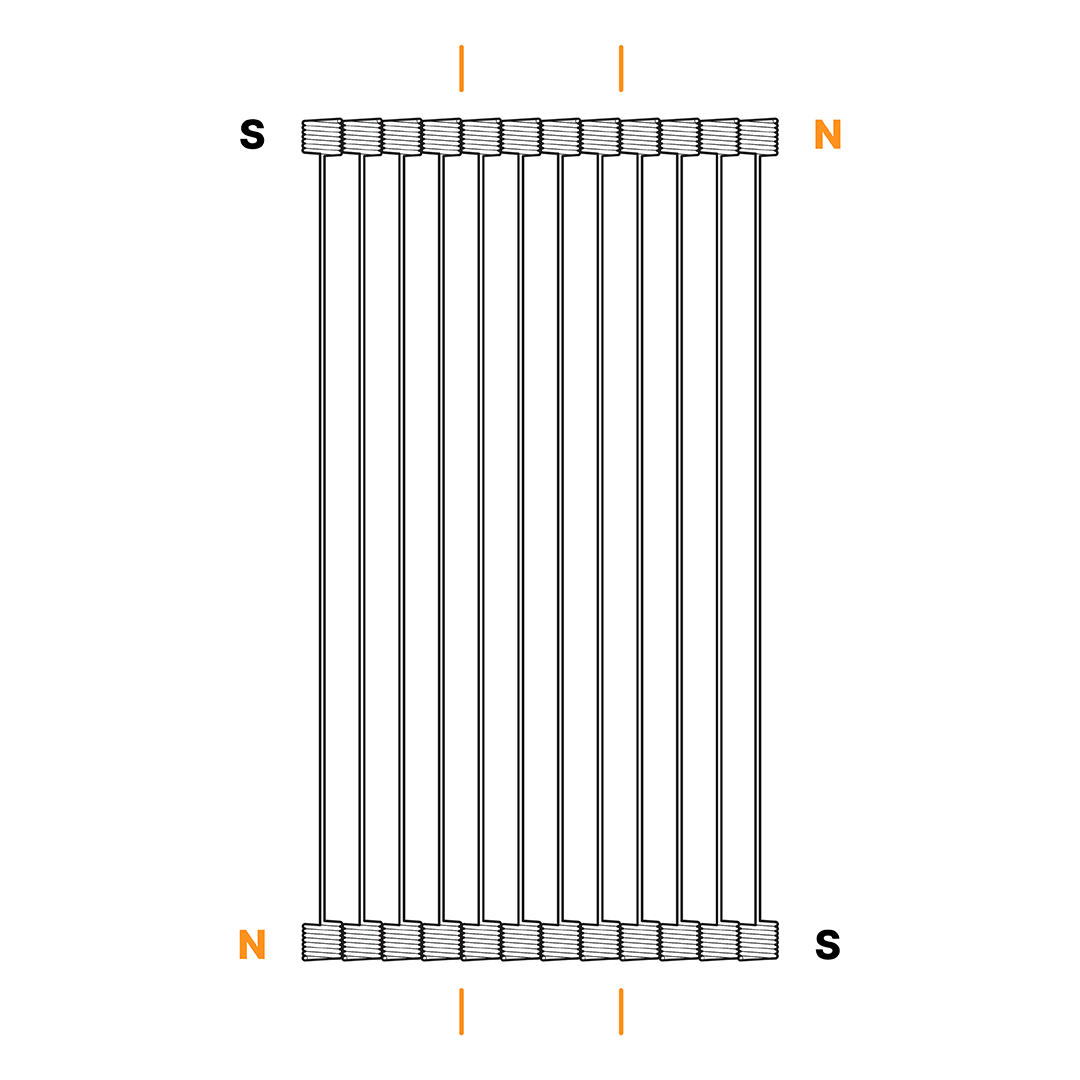
Step 3
Count the number of lines of bars in the block and divide it into three equal parts. This will make it easier to handle and store.
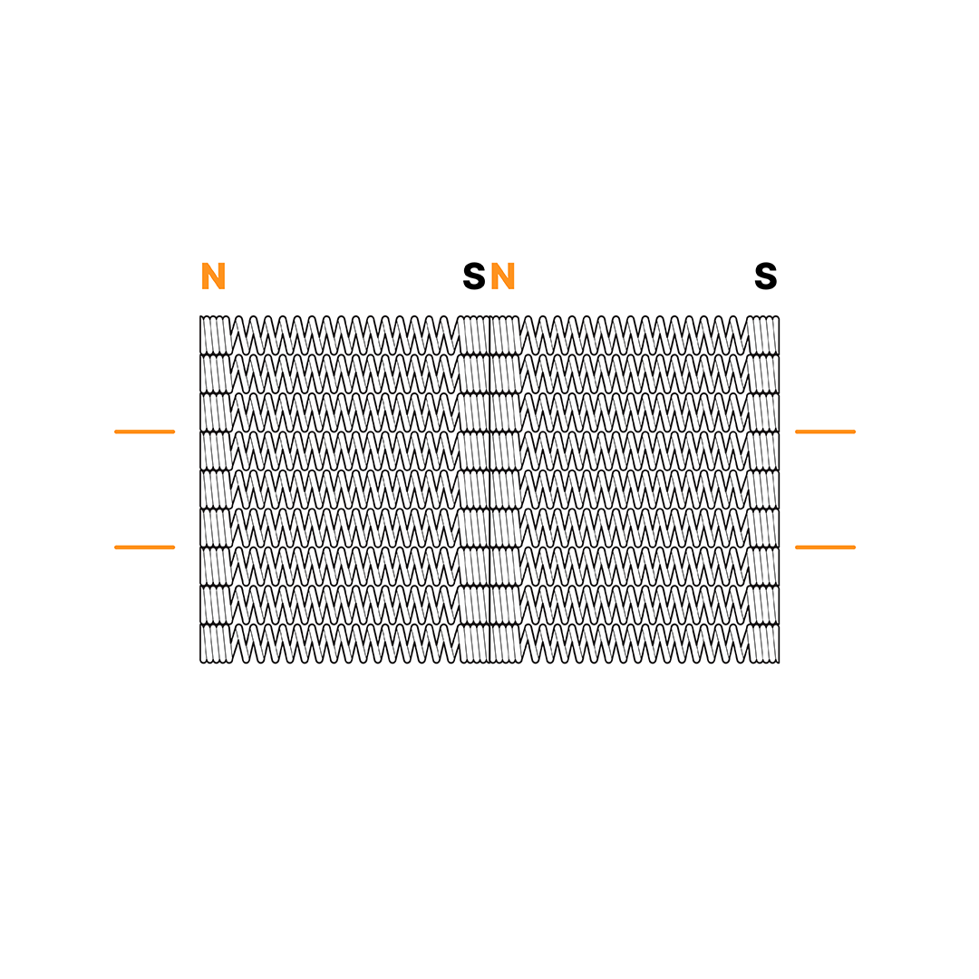
Step 4
Stack the three parts on top of each other. If the blocks are composed of an even number of bar lines, flip the central block before stacking to ensure proper magnet alignment. Finally, place the entire block into its designated insert in the storage box.
Diagonals
Follow a similar procedure for organizing the diagonals.
Step 1
Start by aligning all diagonals side by side. If there is repulsion between two diagonals, simply flip one diagonal to ensure they connect perfectly.
Step 2
Count the number of diagonals in the block and divide it into three equal parts. This will make it easier to handle and store.
Step 3
Stack the three parts on top of each other. If the blocks are composed of an even number of diagonals, flip the central block before stacking to ensure proper magnet alignment. Finally, place the entire block into its designated insert in the storage box.
Assembly and Load Application
Useful information for using Mola 1, Mola 2, Mola 3, and Accessories.
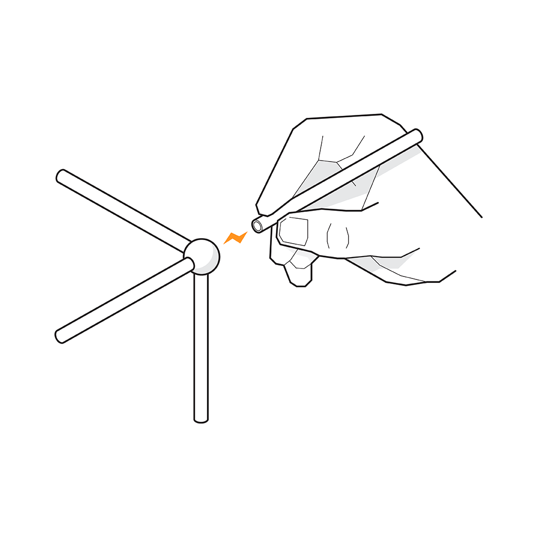
Connecting Components
While positioning any element, it is suggested to hold it by the extremity that will be attached to the structure. This prevents the part from being drawn by other elements.
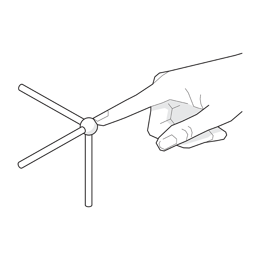
Handling
To remove the parts from the box, when you already have a piece in hand, it is suggested to use the magnet to pinch the parts you want, especially the Connections.
Load Application
The ideal way to apply loads to structures assembled with Mola Structural Kits is through the use of hands. In this way, it is possible to feel the structures through touch, providing a new learning experience.
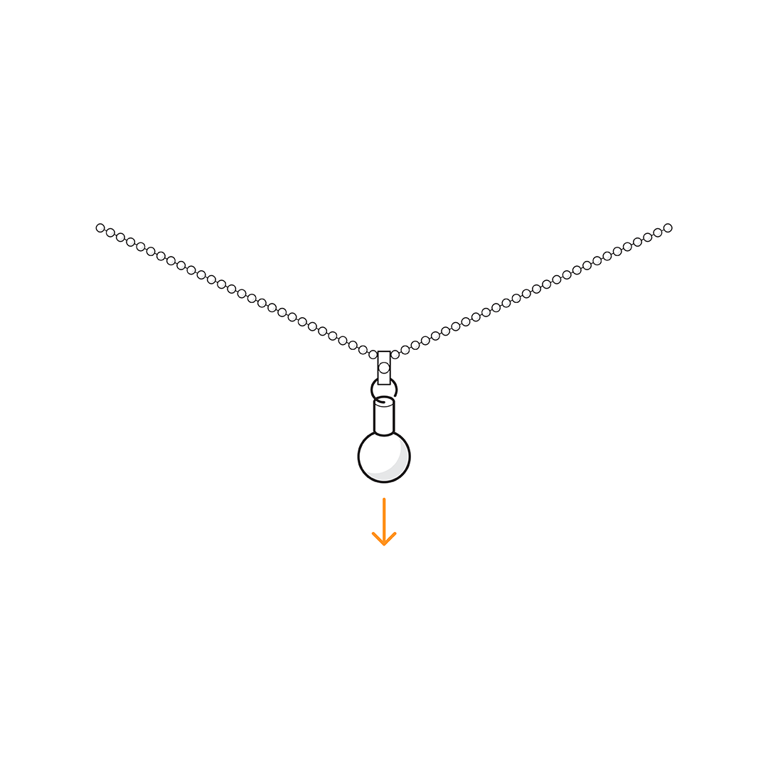
Load Application (Mola 3)
To analyze the behavior of cable elements with Mola Structural Kit 3, you can also apply loads to the structure by using the Connection in combination with the Cable Connection and the Cable Clip Connection.
Ground Plates
Learn the characteristics of the ground plates and their connection with other components.
Following this guidance will help you achieve an accurate and precise foundation setting-out process.
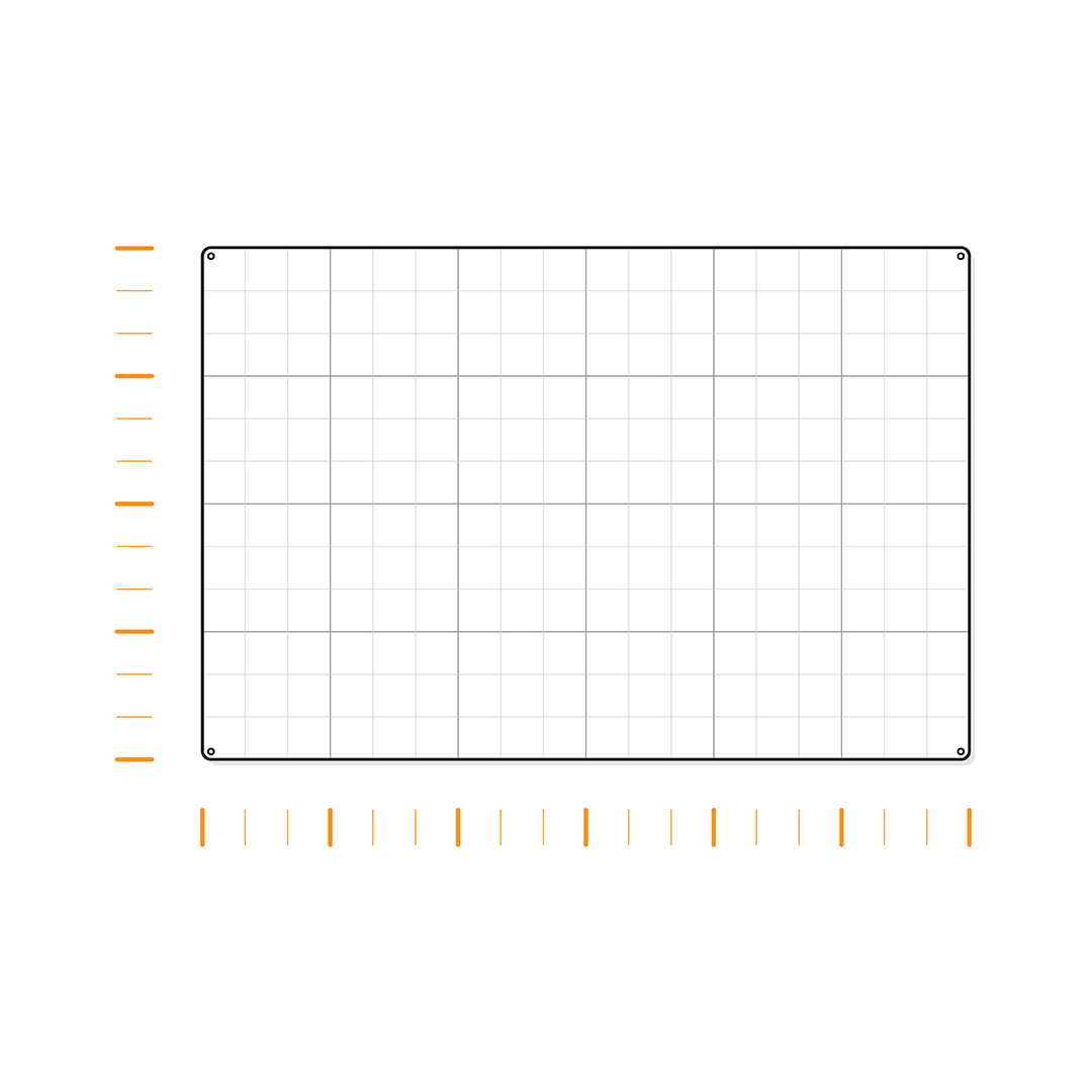
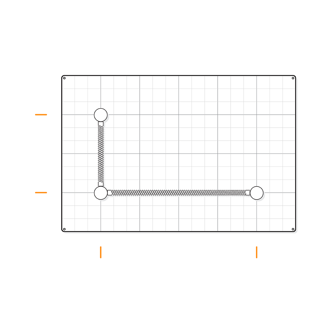
Structural Axis Marks
The Ground Plate represents the ground of a real building. It is designed with line marks that highlight the structural axis of the system.
These lines are not just for aesthetic purposes - they play a key role in ensuring that all components align perfectly, maintaining the structural integrity of your assembly.
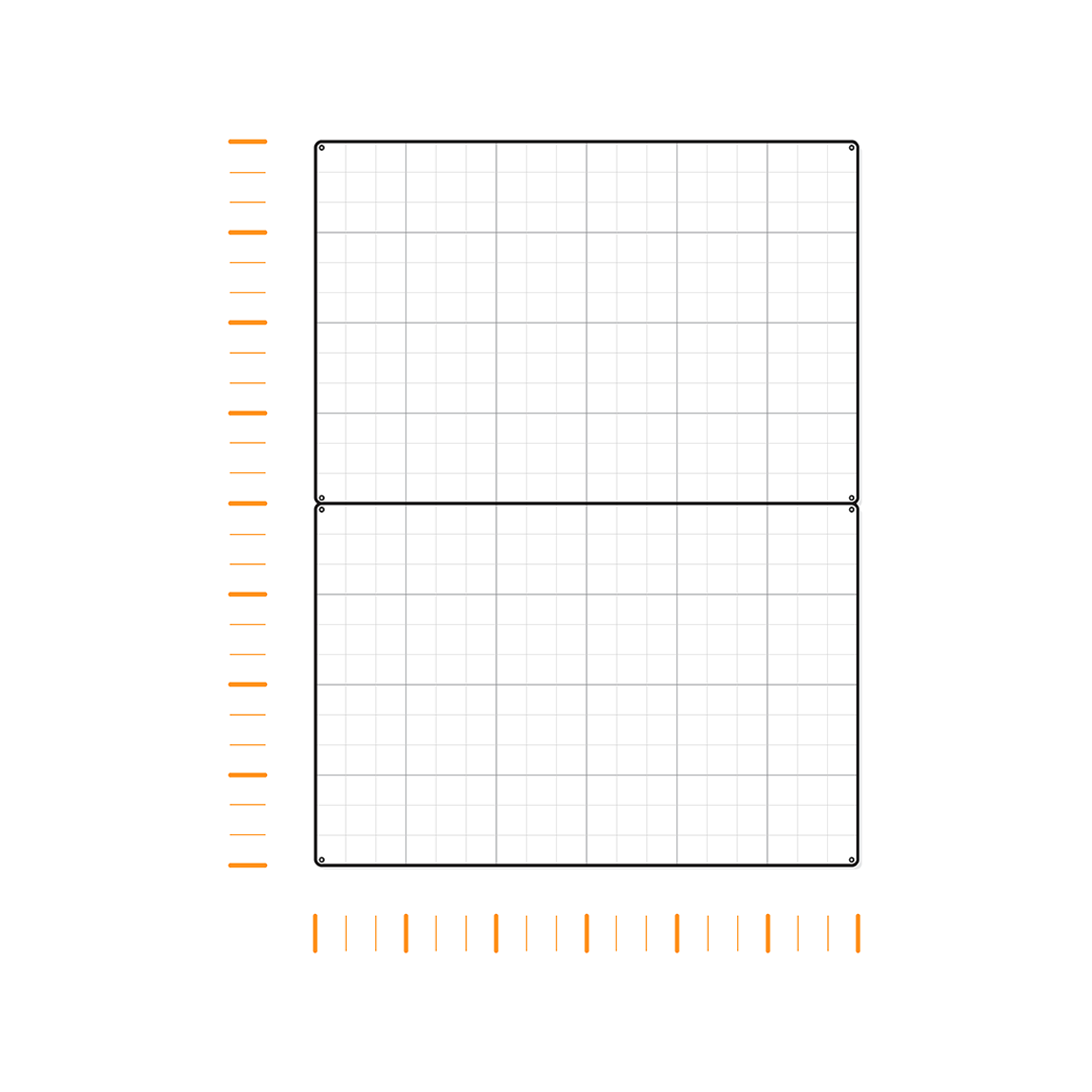
Expanding the Building Area
Combine two or more Ground Plates for a larger building area. Ensure the axis marks of each plate are aligned. This will maintain the modularity of the system, providing a seamless and precise extension for your design.
You can use regular masking tape underneath the Ground Plates to fasten them together.
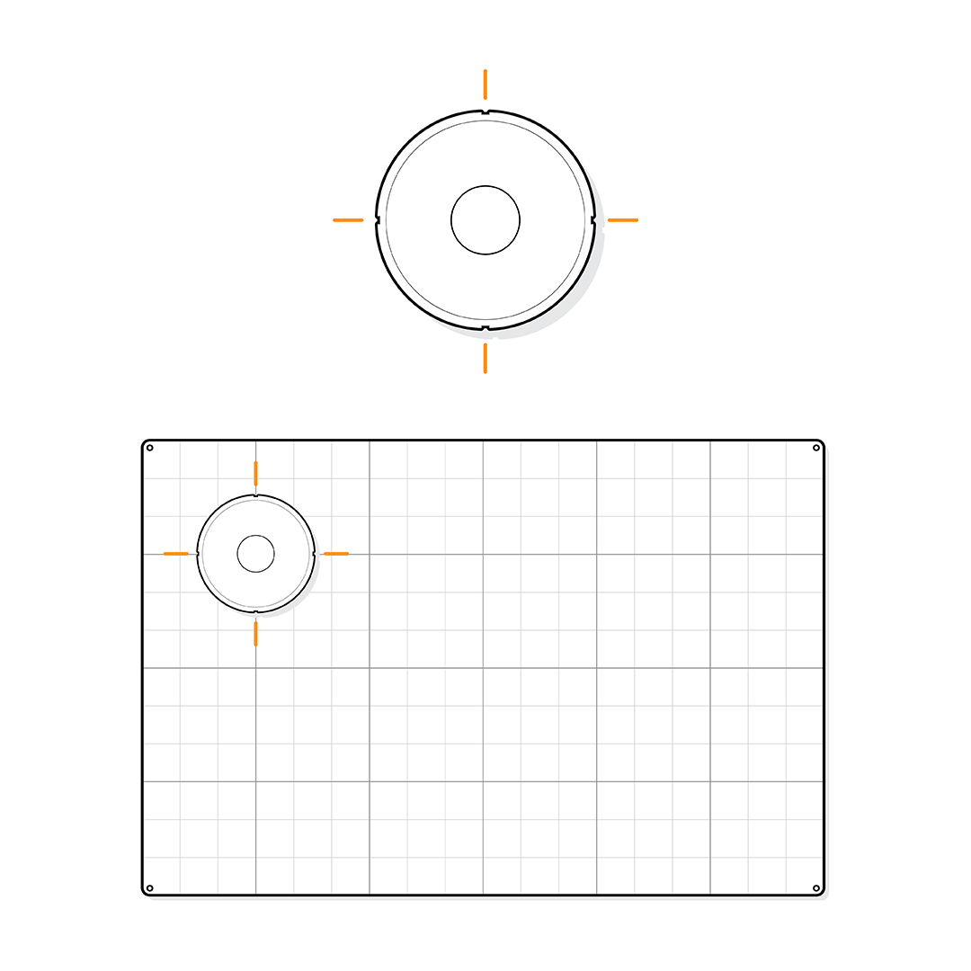
Ground Connections
The Ground Connection acts as the foundation of a building, connecting the structure to the ground. Each Ground Connection has four lateral axis markings for proper alignment and positioning.
Align its lateral markings with the axis marks on the Ground Plate. This ensures that the component is correctly positioned, providing a precise foundation for your building.
Setting Out Foundations
All components of the system are designed based on the structural axis modulation. By aligning different components, such as bars, with these axis marks on the Ground Plate, you can accurately determine the correct positions for the structure's foundations.
This setting-out procedure will function as the process of transferring dimensions from a drawing plan to the actual construction site.
Mola Structural Kit 3
Learn about the characteristics of some components in the Mola Structural Kit 3.
Follow these tips to build your cable structures with greater precision.
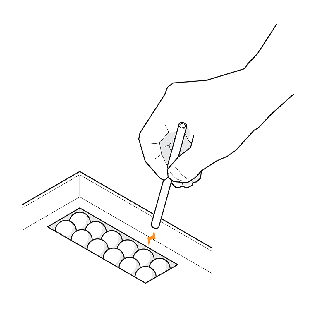
Measuring Cables
In the Mola 3 book/manual, specific cable lengths are suggested for each example of structural systems to be assembled.
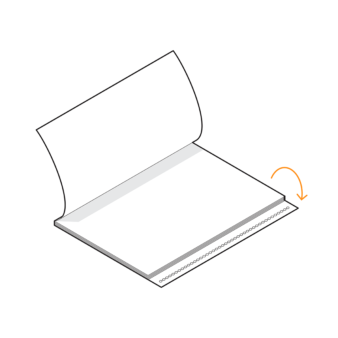
Use the cable measurement ruler located on the back cover to measure the exact length of the cable, taking into account the number of balls, without having to count them one by one.
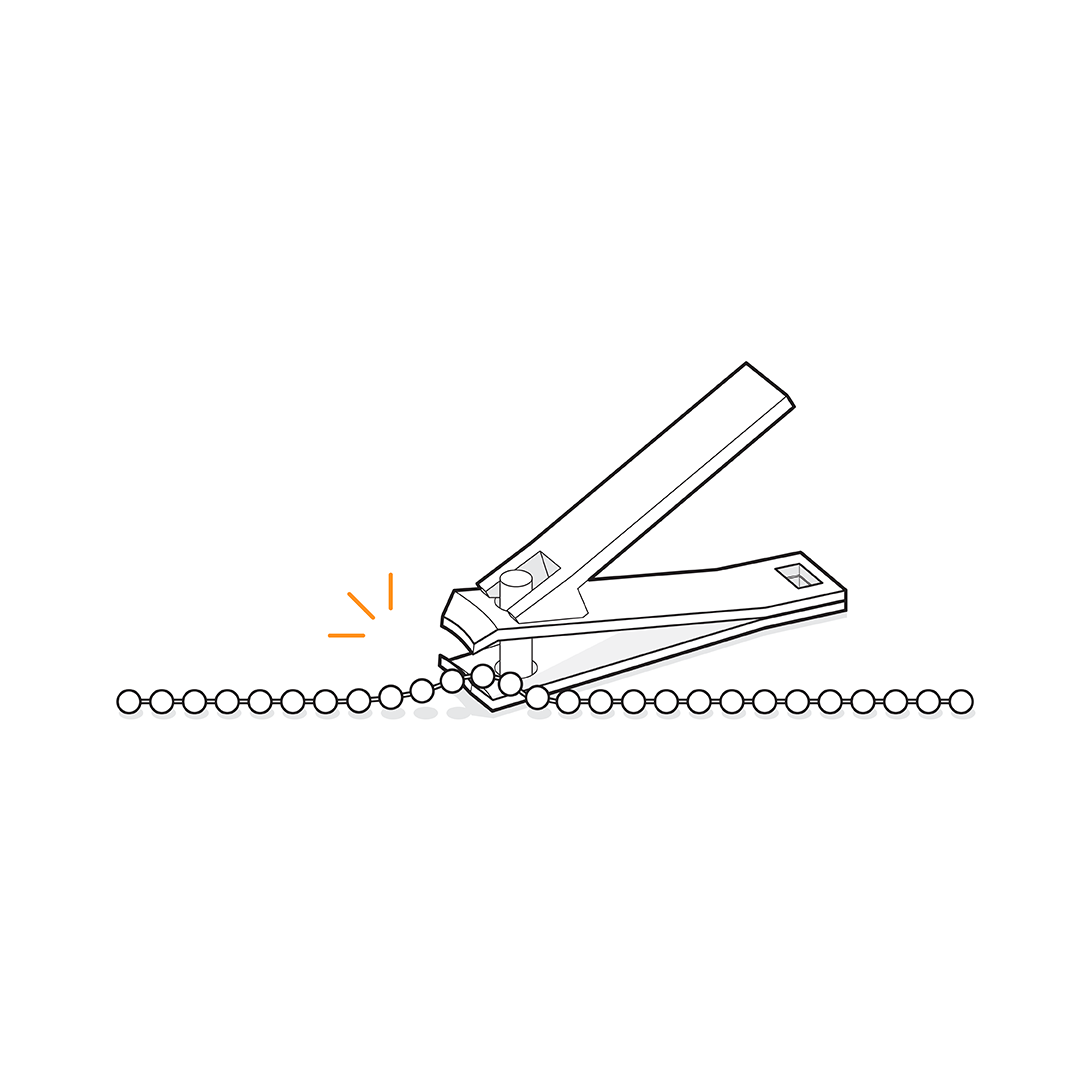
Cutting Cables
Use the cutting tool to trim the cable to your desired length. Before doing so, check if you already have cables of the same length from previous use. This way, you can make better use of the cables, enabling you to assemble all the structures presented in the book/manual.
If needed, you can also order Cable Replacement Parts from our online store >
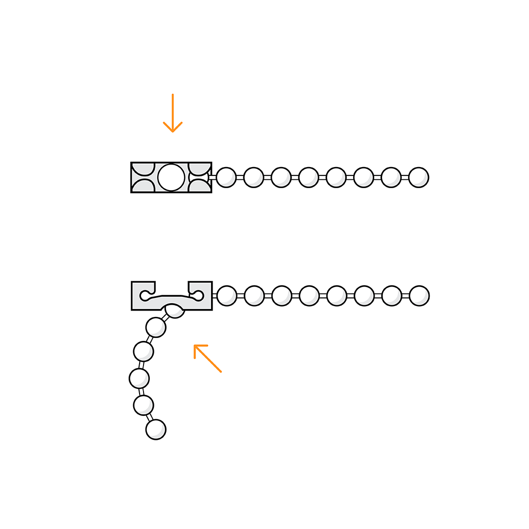
Cable Clip
The attachment of cables to the Mola Structural System involves combining various connection elements.
The Cable Clip features a central hole that allows connection to any ball along the cable, not just the end. This versatility eliminates the need to cut the cable to precise lengths for assembly. Simply leave a portion of the cable outside the Cable Clip to facilitate structure assembly.
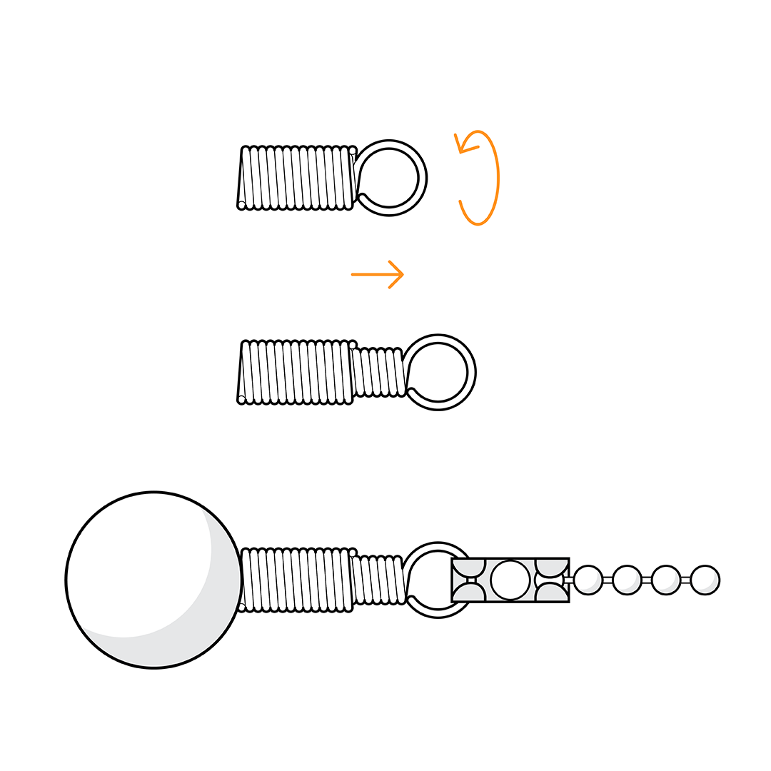
Cable Connection
The Cable Connection is crucial for attaching cables to the system. It has two threaded-together parts: the external part with a magnet for attaching to the structure and the internal part with a ring for connecting the Cable Clip. It also functions as a tensioner, allowing you to make final adjustments to the cable length and maintain proper tension. Simply hold the magnet part and twist the ring part to make the cable longer or shorter, ensuring a precise assembly process.
We’d love to hear from you!
Share Your Assembly Tips
Share your tips and tricks for using Mola and help others build better.
Your insights and experiences can inspire and guide our community.